
Automotive EMC Testing: CISPR 25, ISO 11452-2 And Equivalent Standards, Part 1
- Home
- Automotive EMC Testing: CISPR 25, ISO 11452-2 And Equivalent Standards, Part 1

EMC Standards and Chamber Testing for Automotive Components
This two-part article is an update of the original article authored by Dr. Vince Rodriguez, then with ETS‑Lindgren. An earlier update was published in the February 2016 issue of In Compliance Magazine.
Automotive standards addressing electromagnetic compatibility (EMC) are developed mainly by CISPR, ISO, and SAE. CISPR and ISO are organizations that develop and maintain standards for use at the international level. SAE develops and maintains standards mainly for use in North America. In the past, SAE developed many EMC standards which were eventually submitted to CISPR and ISO for consideration as an international standard. As the SAE standards become international standards, the equivalent SAE standard is then withdrawn as a complete standard and reserved for use to document differences from the international standard.
Each vehicle manufacturer has internal corporate standards that specify the testing, severity, and sensitivity levels that components used in their vehicles, and the complete vehicle must meet. As with the government standards, these documents usually refer to the CISPR and ISO documents with differences in scope or test levels. In the past, a vehicle manufacturer based in the U.S. referenced SAE documents in their corporate standards, today most U.S.-based vehicle manufacturers market worldwide. Therefore, they reference CISPR and ISO standards in their internal corporate standard, and this is also true for other established and emerging manufacturers.
– Partner Content –
VSWR and its Effects on Power Amplifiers
Voltage Standing Wave Ratio results from an impedance mismatch between a source (an amplifier) and a load (test application). This mismatch can influence the performance of the source.
CISPR/D is responsible for developing and maintaining the standards used to measure the emissions produced by vehicles and their components. ISO/TC22/SC32/WG3 is responsible for developing and maintaining the standards used for immunity testing of vehicles and their components. ISO standards for the vehicle industry are mainly broken into two categories, vehicle (ISO 11451-xx) or component (ISO 11452-xx, ISO 7637‑xx). Table 1 provides an overview of the CISPR and ISO EMC standards for the automotive industry.
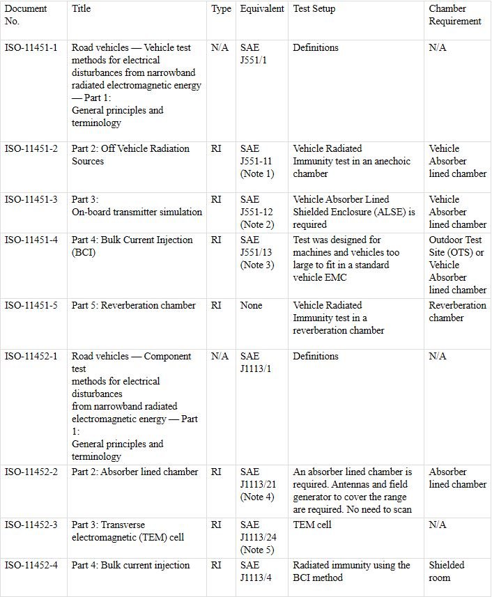

Note 1 SAE J551‑11 Withdrawn as a complete standard and reserved for use to document differences from ISO 11451‑2. At the present time J551‑11 is not used.
Note 2 SAE J551‑12 Withdrawn as a complete standard and reserved for use to document differences from ISO 11451‑3. At the present time J551‑12 is not used.
Note 3 SAE J551‑13 Withdrawn as a complete standard and reserved for use to document differences from ISO 11451‑4. At the present time J551‑13 is not used.
Note 4 SAE J1113‑21 Withdrawn as a complete standard and reserved for use to document differences from ISO 11452‑2. At the present time J1113‑21 is not used.
Note 5 SAE J1113‑24 Withdrawn as a complete standard and reserved for use to document differences from ISO 11452‑3. At the present time J1113‑24 is not used.
Note 6 SAE J1113‑23 This standard has been withdrawn. Note 7 SAE J1113‑3 Withdrawn as a complete standard and reserved for use to document differences from ISO 11452‑7. At the present time J1113‑3 is not used.
Note 8 SAE J1113‑22 Withdrawn as a complete standard and reserved for use to document differences from ISO 11452‑8. At the present time J1113‑22 is not used.
Note 9 SAE J1113‑2 Withdrawn as a complete standard and reserved for use to document differences from ISO 11452‑10. At the present time J1113‑2 is not used.
Note 10 SAE J1113‑28 Withdrawn as a complete standard and reserved for use to document differences from ISO 11452‑11. At the present time J1113‑28 is not used.
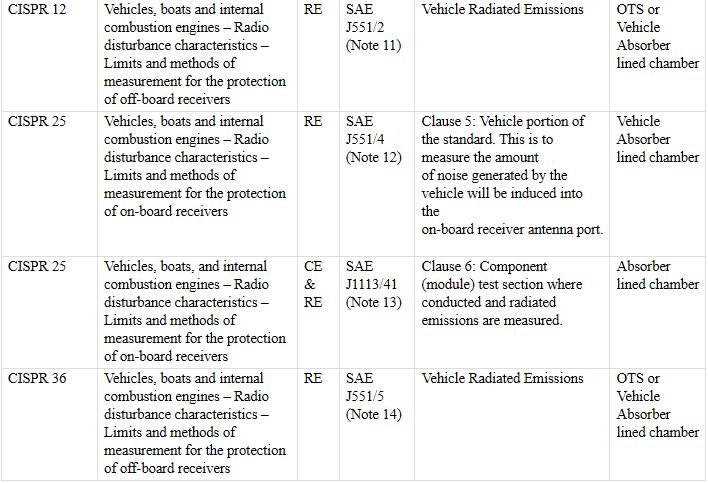
Note 11 SAE J551‑2 Withdrawn as a complete standard and reserved for use to document differences from CISPR 12. At the present time J551‑2 is not used.
Note 12 SAE J551‑4 Withdrawn as a complete standard and reserved for use to document differences from CISPR 25. At the present time J551‑4 is not used.
Note 13 SAE J1113‑41 Withdrawn as a complete standard and reserved for use to document differences from CISPR 25. At the present time J1113‑41 is not used.
Note 14 SAE J551‑5 Withdrawn as a complete standard and reserved for use to document differences from CISPR 36. At the present time J551‑5 is not used.
Table 1: Some of the main CISPR and ISO EMC standards for the automotive industry
As with the ISO EMC standards, SAE EMC standards are mainly broken into two categories, vehicle (SAE J551-xx) and component (SAE J1113‑xx). As can be seen in the notes of Table 1, many of the SAE standards are inactive because they have been withdrawn as complete standards and reserved for use to document differences from the international standards. Table 2 on page 12 does not show all the EMC standards related to automotive published by the SAE, but it gives an overview of the main standards and cross-references to the equivalent ISO or CISPR document. Table 2 shows the main SAE standards that are still active for both vehicle components and vehicles.
As with Table 1, Table 2 is not intended to show all the different parts of the standard, but to show the complexity of the standard documents and the many parts and methods that are covered under them. As mentioned above, government standards and directives in many cases refer to the CISPR or ISO methods. 2004/104/EC, which surpassed 95/54 EC, is a European directive for vehicle EMC. Its sections related to automotive components follow the directions given in the CISPR 25 document.
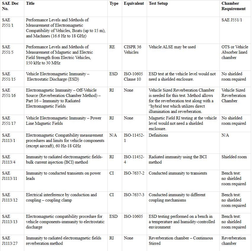
Table 2: Some additional active SAE automotive EMC standards
CISPR 12, CISPR 25, and CISPR 36
CISPR 12 and CISPR 36 deal with “radio disturbance characteristics for the protection of off-board receivers” [1] [6]. CISPR 25 deals with “radio disturbance characteristics for the protection of receivers used on-board vehicles, boats and on devices” [2]. It is important to remember that CISPR 12 and CISPR 36 (the test methods and/or limits) are commonly used for regulatory purposes. The regulatory bodies want to make sure that an item with an internal combustion engine or electric propulsion system does not cause unwanted interference with TV and radio reception when it drives past (or is used nearby) a residence or business. These standards also cover electrically driven vehicles while stationary and in the charging mode of operation. CISPR 25 is not typically used for regulatory purposes, it is commonly used by vehicle manufacturers to assure good performance of receivers mounted on‑board the vehicle. If the radio mounted in the vehicle, boat or other device does not perform reliably, then consumer satisfaction and ultimately product sales could suffer.
Both CISPR 12 and CISPR 25 deal with automobiles (vehicles that operate on land) powered by internal combustion engines or an electric propulsion system, boats (vehicles that operate on the surface of water) powered by internal combustion engines, and devices powered by internal combustion engines (but not necessarily for the transport of people). This last category includes compressors, chainsaws, garden equipment, etc. CISPR 12 would apply to all of these devices since they could affect the performance of nearby (off-board) receivers. CISPR 36 only applies to road vehicles driven by an electric propulsion system. It should be noted that CISPR 25 should only be considered for items that contain on-board receivers. As an example, a chainsaw with an internal combustion engine (but with no on-board receivers) would need to meet the requirements of CISPR 12, but CISPR 25 would not apply to this chainsaw since it does not utilize any on-board receivers.
CISPR 12 radiated emissions measurements are made at either 3-meter or 10-meter test distances (although the limits are for the protection of off-board receivers at a distance ≥ 10 meters). The measurements are normally done on an outdoor test site (OTS) or in an absorber-lined shielded enclosure (ALSE) if the ALSE can be correlated to an OTS. Measurements for boats can also be made on the water. The correlation of the ALSE to an OTS has been a point of discussion over the past few years within the group of experts who are responsible for the maintenance of CISPR 12. The specification currently does not provide a method to achieve this correlation. A working group has been tasked with developing a method to validate an ALSE, OATS, or OTS that could be used for vehicle measurements. The plan is to add a site validation annex to CISPR 12 7th Edition when it is published.
CISPR 36 radiated emissions measurements are made at 3-meter test distance with a loop antenna (although the limits are for the protection of off-board receivers at a distance ≥ 10 meters). The magnetic field emissions measurements are normally done on an OTS, open area test site (OATS), or in an ALSE. Site correlation/validation is currently not covered in CISPR 36. However, site validation is being considered as a work item for future editions.
CISPR 25 has two parts. One part deals with a full vehicle or system test in which the antennas mounted on the vehicle are used to sense the noise generated by the different electric and electronic systems mounted on the same vehicle. This test shows how much noise generated by the vehicle will be introduced into the radio antenna port (sort of a self-immunity test). The other section of the standard deals with conducted and radiated measurements of vehicle components and modules. In this article, we are going to concentrate on the module radiated emissions test section of CISPR 25, and only briefly highlight some of the additions needed to support electric vehicles. More specifically, this article will concentrate on the chamber requirements for the standard.
CISPR 25 states that the electromagnetic noise level in the test area has to be 6 dB lower than the lowest level being measured. Some of the radiated emissions limits found in CISPR 25 are as low as 18 dB (µV/m). This means that the ambient noise must be 12 dB (µV/m) maximum for a compliant environment. An RF-shielded room is typically used to keep RF signals from the external environment out of the test area so that the equipment under test (EUT) remains the dominant source of any radiated interference.
Although the shielded room is too small to support resonant modes at low frequencies, the number of modes increases with frequencies above the cut off of the chamber. When these resonant modes appear, they can add significant errors to the measurements. To reduce these errors, the shielded room covered with RF absorber material on its ceiling and interior walls greatly suppresses internal reflections so that the dominant coupling path is between the EUT and measurement antenna. By adding RF absorber to the walls and ceiling of the shielded room, the room becomes an absorber-lined shielded enclosure (ALSE). CISPR 25 in its current version (Ed 5:2021) covers a frequency range of 150 kHz to 5.95 GHz and to date absorber technology is unable to provide appreciable absorption at levels down in the 150 kHz range. One beneficial consequence of the low measurement frequency and the 1-meter measurement distance is the fact that the chamber sizes are electrically small at these low frequencies, so no significant resonant behavior appears. Therefore, the standard concentrates on absorber performance at 70 MHz and above. The standard requires that the absorber used must have better than -6 dB absorption at normal incidence. To achieve these levels, there are several types of absorber technology on the market today.
One of the most efficient and cost-effective is a polystyrene-based absorber that combines a high-performance ferrite tile with a polystyrene EMC absorber, having a 60cm x 60cm base and 60cm height. The main absorber substrate is based on expanded polystyrene (EPS), which is volumetrically loaded with lossy materials, and environmentally friendly fire retardants. Advanced uniform loading in the manufacturing process results in superior RF performance and excellent absorption uniformity. The closed cell structure of this type of absorber makes it suitable for use even in high-humidity environments. These features all contribute to providing a better controlled and predictable chamber test environment. Figure 3 presents the performance of one type of hybrid polystyrene absorber.
An alternative polyurethane absorber typically 36 inches (1m) in depth, EHP 36, can be used with improved high frequency performance due largely to the increased material length. But, without the benefit of the matching ferrite material used in the hybrid, the polyurethane only absorber suffers from reduced low frequency performance. Figure 4 shows the typical performance of this material and its compliance with the CISPR 25 limit.
The layout and dimensions of the typical CISPR 25 ALSE is guided by the standard. Several guidelines must be followed when sizing the chamber and the starting point is the EUT, which determines the size of the test bench. Figure 5 shows a typical test bench used in a CISPR 25 and ISO 11452-2 type chamber.
As Figure 5 shows, the bench must accommodate the largest EUT and all the cables that are needed to power and communicate with the device. The cables are routed in a cable harness that is positioned along the front edge of the bench. The cable harness itself is a significant component of the EUT and is the main component illuminated by the measurement antenna since at lower frequencies (frequencies for which the device under test is electrically small) the main coupling to radiated fields will occur through the cables feeding the device. This same procedure is used in MIL-STD 461 [3] and in ISO 11452 [4] and as shown in the illustration, a line impedance stabilization network is used to provide a defined impedance for the power to the device.
Figure 6 shows how the size of the bench is determined. The ground plane bench must extend all the way to the shield and in most cases, it is grounded to the wall of the shielded room. Grounding of the ground plane to the wall of the ALSE, especially if the chamber utilizes hybrid (ferrite/foam) absorbing material, has shown to reduce measurement system resonant conditions that may occur in the 10-70 MHz frequency range. The standard, however, does permit the bench to be grounded to the floor as an alternative.
As defined in CISPR 25, the minimum width of the reference ground plane (bench) for radiated emissions shall be 1000 mm, the minimum length of the ground plane for radiated emissions shall be 2000 mm, or the length needed to support the entire EUT plus 200 mm, whichever is larger.
The minimum overall dimensions of the compliant chamber are determined by a series of dimensional relationships based primarily on the size of the test bench. With the use of a hybrid absorber with a depth of 60 cm to line the walls and ceiling of the chamber, Figure 7 shows that the width and length of the chamber is determined by the length of the absorber material with a one-meter space left between the bench (actually the DUT) and the tips of the absorbing material. For chambers that will also be used for e-motor testing, the motor is also part of the EUT. In some cases, the motor is supported on a separate structure adjacent to the test bench for mechanical reasons as shown in Figure 8. In this case, it still needs to be connected to the ground plane so in effect it will be an extension of the ground plane bench and subject to the minimum distances as defined in the standard.
For the height and the length of the chamber, CISPR 25 further defines the separation distances to be followed in determining the minimum space needed. The first and most critical is the test distance where emissions are to be measured at a minimum distance of 1 m from the cable harness to the antenna.
The other rule states that no part of the antenna can be closer than 1 m away from the tips of the absorbing material. These rules and recommended antennas define the length and height of the chamber. The 1 m distance to the cable harness is measured from the axis of the antenna elements for the monopole rod and the biconical antenna. For the log periodic dipole array (LPDA), the distance is measured from the tip of the antenna. Finally, for the horn antennas the distance is measured from the front face or aperture plane of the antenna. The longest antenna is usually the LPDA. A typical LPDA for the 200 MHz to 1 GHz range is about 1 m in overall length. In addition to the 1 m test distance and the 1 m for the antenna length, we have a 1 m clearance from the back of the antenna to the tips of the absorber. Figure 8 also shows the reference distances for an LPDA and bicon antennas in the chamber for the CISPR 25 setup.
The height of the chamber will be driven by the longest antenna. The longest vertical antenna is usually the active rod monopole. The monopole is used with an extremely electrically small ground plane. Per the standard, the monopole rod is about 80 cm in length and it is positioned such that the ground plane is at the same level as the bench which as Figure 5 suggests is nominally 90 cm in height. The 1 m rule for the separation between the antenna and the absorber tip will again determine the minimum height of the chamber as shown in F
With the components discussed in the previous sections, a chamber lined with 0.6m long hybrid absorber with a size of 5.2 meters wide by 6.2 meters long and 3.6 meters high will meet the minimum size requirements for performing compliant CISPR 25 tests. And, as we will see in the next section of this article, this chamber will also meet the requirements of ISO 11452‑2. Furthermore, since this is a shielded environment, most of the tests defined in standards requiring a shielded room can be performed inside the chamber described in the present section.
The CISPR 25 document prepared by the CISPR organization, and the requirements and guidelines on antennas and receivers, are already comprehensively defined in the CISPR 16-1-4 document [5]. The recommended antenna types used for the CISPR 25 measurements are therefore cross-referenced to the CISPR 16 document. For low frequencies, an active rod monopole antenna is preferred. At frequencies between 30 MHz and 200 MHz, a typical biconical antenna is the recommended antenna. From 200 MHz to 1 GHz, the antenna of choice is an LPDA and finally, from 1 to 5.95 GHz, the dual ridge horn (DRH) antenna can be a more compact and efficient antenna that easily meets the cross pole requirements of the standard, although lower gain LPDAs can still be used. It should be noted that bi-log antennas are not allowed for CISPR 25 measurements and all references to the bi-log antenna have been removed from CISPR 25 5th Edition.
CISPR 25 5th Edition contains an annex (Annex I) that provides methods to validate the performance of an ALSE used for component-level radiated emission tests. The ALSE validation annex (Annex J) in CISPR 25 4th Edition contained two methods (one method based upon reference measurements and another method based upon modeling) for validating the ALSE. However, after the 4th Edition validation methods were used for several years, the experts responsible for CISPR 25 decided to include only the chamber validation method based upon modeling for CISPR 25 5th Edition. The ALSE validation method in CISPR 25 currently covers the frequency range of 150 kHz to 1 GHz. However, this remains an informative annex and experts are discussing ALSE validation methods >1GHz for future editions of CISPR 25.
As mentioned at the beginning of the article, CISPR 25 also covers the measurement of emissions received by a vehicle antenna for a full vehicle setup. CISPR 25 5th Edition contains special setups to be used for the testing of electric vehicles (EVs) and hybrid electric vehicles (HEVs) and the modules (inverters, batteries, etc.) to be used on EVs and HEVs. The committee found that special testing and limits are required for the testing of these electric-driven vehicles and their components.
These vehicles represent a special case since there are high currents and voltages involved not only in normal operation but also during charging cycles. There will be more detailed information on the measurement setups to be used for EV and HEV measurements under different connection and charging scenarios. The testing adds new conditions for when the vehicle is not being driven, but connected to the mains or a charging station. This is currently already required as part of the European directive ECE Regulation 10, which outlines the EMC requirements for wheeled vehicles marketed in the European Union. Although ECE Reg 10 has its own limits for vehicle and ESA testing, it references both CISPR 25 and CISPR 12 for test setups and measurement techniques.
ISO 11452-2
ISO 11452-2 is a vehicle component immunity standard that applies to the 200 MHz to 18 GHz range. This standard, like many automotive, military, and aerospace standards, calls for moderately high fields to be generated. Table 3 shows the severity levels. At frequencies below 200 MHz, antennas get physically larger and also less efficient. For frequencies below 200 MHz, the standard recommends the methods stated in parts 4, 3, and 5 of the ISO 11452 standard. Those sections describe the bulk current injection, TEM, and stripline test methods. These other methods are far more efficient and economical to test for immunity to high fields.

Table 3: ISO 11452-2 severity levels
The ISO 11452-2 standard also requires that the tests be performed in an ALSE. As is common with most immunity measurements, the intent of the test is to produce RF field levels that can be disruptive or damaging to the EUT; the shielded room removes the risk of unintended disruption to other sensitive devices or equipment outside of the test region. In the US, as in most other countries, there are limits on the radiation of energy without licenses, at frequencies that could affect licensed broadcasts.
These tests are conducted at frequencies above 200 MHz and as discussed previously, the chance of resonant modes being developed inside the shield room is increased, so to reduce measurement errors the use of an absorber is required. The chamber is treated such that the reflectivity in the area of the EUT is -10 dB. Figures 3 and 4 show that for the 200 MHz to 18 GHz range, the -10 dB level is higher than the typical reflectivity of the recommended materials. This means that the same absorber used in the CISPR 25 chamber can be used in the ISO 11452-2 chamber, with the relevant guidance on minimal separation distances between DUT, absorbers, and antennas. Antenna selection is in keeping with the need to generate the required field levels in the most effective and efficient manner given the cost of amplifiers. It is recommended that a dual ridge horn antenna be used for the 200 MHz to 2 GHz range. Above that, octave horns and standard gain horns with high gain are the preferred antenna choice.
Conclusion
In Part 1 of this article, the reader has been introduced to the two main standards for automotive vehicles and components with an overview of the revision status of these and several related standards produced by CISPR and ISO. In Part 2 of this article, we will concentrate on designing a chamber to meet the requirements of CISPR 25 and show how the same chamber can be used for ISO 11452-2.