
EMC Problems in Production and How to Avoid Them
Original White Paper Published By: LAPP
Identifying and predicting potential EMC problems is complex – LAPP supports the EMC supply chain by offering high-quality cabling and connectivity solutions.
1. EMC Problems are Increasing
The demand for integrated electromagnetically compatible (EMC) solutions from plant and mechanical engineering is growing by around 6-7 percent worldwide (source: among others, from studies by Bloomberg, GlobeNewswire, Transparency Market Research, Markets and Markets (2022)).

The reason for this is that the power and data density in the “Smart Factory” is constantly increasing. Four developments are largely responsible for this:
- More frequency converters to improve energy efficiency with much faster switching frequencies at the same time
- Increased susceptibility to interference due to more data transmission with less energy
- More electronic devices in a tight space
- Increasing interactions by opening up new frequency ranges at ever closer distances
In the worst case scenario, even a small fault can cause the entire system to fail. Preventing this is the top priority. However, this requires a good understanding of the system and the selection of the right components.
2. Definition of Electromagnetic Compatibility (EMC)
In the EMC Directive 2014/30/EU, Article 3, electromagnetic compatibility is defined as “[…] the ability of a piece of equipment to operate satisfactorily in its electromagnetic environment without causing electromagnetic interference (EMI), which would be unacceptable for other equipment in this environment.”
This interference can either be of natural origin, e.g. caused by lightning strikes, or of technical origin, such as electromagnetic effects caused by switching pulses or incorrect or missing earthing. Something that is just a bit disruptive, like FM radio reception interference, can have dramatic consequences in medical technology.
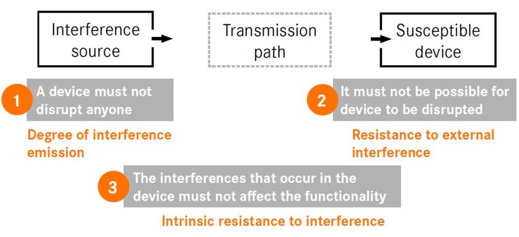
The electrotechnical theory behind the EMC phenomenon can be abstracted from three factors: interference source, interference sink and a coupling mechanism between the two.
The concept of EMC in brief

Figure 1: Three factors are relevant for electromagnetic compatibility
The transmission path between the interference source and the interference sink is also known as electromagnetic coupling. There are four different types, each of which can occur individually or as a mixed form:
- Galvanic coupling through common conductors of different circuits. This is the case, for example, when protective earths of devices or the shielding of cables are linked to one another and compensating currents can flow through them.
- Capacitive coupling of electric fields in the case of conductors very close together in a cable or cable duct or in the case of conducting paths routed in parallel on a circuit board. The effect occurs primarily at high frequencies or switching at high voltages.
- Inductive coupling due to magnetic fields, particularly at low frequencies. The underlying physical principle is used in the transformer where it is desirable. The magnetic coupling undesirably occurs, for example, with parallel conductors in connection with high load currents.
- Radiation interference due to insufficiently screened cables or devices, which then work like an antenna. This effect only occurs at frequencies greater than 1 MHz.
![]()
Figure 2: Four possible transmission paths for electromagnetic interference
3. Power Electronics, Pulse Width Modulation and the Problem of Leakage Currents
In many industrial systems, but also in many household appliances, motors are now controlled with frequency converters. Pulse width modulation (PWM) allows the motor speed to be adjusted continuously and saves energy. In order to keep energy losses as low as possible, manufacturers strive for the shortest possible switching times.

Figure 3: Principle diagram of pulse width modulation
However, this leads to steep slopes in the voltage rise and fall, which results in high-frequency voltage components. These couple to metallic structures via the parasitic earth capacitances of the motor, the heat sink of the frequency converter itself or via the motor cable (Fig. 4) and stimulate disruptive PE/PA currents
there (PE = protective earth, PA = equipotential bonding).
Once these interference currents are coupled into the grounding or equipotential bonding network, they wander through the system, preferably via large-area and metallic structures. There they disrupt data communication and sensitive devices, heat up components in EMC filters, trigger residual current circuit breakers, increase wear on bearings and accelerate corrosion on steel supports or water pipes.
 Figure 4: Main coupling paths for PE/PA interference currents
From the point of view of a cable manufacturer, two frequency ranges are primarily relevant:
- Low-frequency range 0–50 Hz: High influence of mains voltage. In order to improve the design of an electrical cable, measures relating to symmetry and/or magnetic coupling (inductance) within a cable are required.
- Medium-frequency range 2 kHz–200 kHz: This is typically where the basic clock frequency of a frequency converter lies (2–8 kHz). According to Fourier theory, harmonic overlays form with increasing frequency (10 kHz–200 kHz). The height of the “needles” is mainly determined by the electrical coupling within the motor cable – i.e. by the effective capacitances. That’s why motor connection cables usually use polyethylene (PE) or polypropylene (PP) as core insulation material in order to reduce the electrical coupling within the cable.

Figure 5: Typical spectral distribution of parasitic currents on the PE/PA grid, measured at a 55 kW pump
In the research project “Causes, propagation paths and interactions of PE/PA flows and modelling of components” (“PEPA” for short) in the 6th energy research programme of the Federal Ministry for Economic Affairs and Climate Action, several partners – including LAPP – researched this topic. The aim of the project was to use simulation to predict PE/PA currents, record and investigate them, and to investigate measures to limit these currents within machines and plants.
4. How Cables Become Electromagnetically Compatible
Electrotechnically passive products such as cables, wires, cable glands and connectors are “components without a direct function” as per the Electromagnetic Compatibility of Equipment Act and therefore do not fall within the scope of the EMC Directive 2014/30/EU.
Instead, EMC-related requirements for some shielded cable types are part of the European or national cable design standards. The challenge is to design them in such a way that they do not contribute to electromagnetic interference, i.e. they do not record, forward or even transmit electromagnetic interference.
Simple example: A data cable must be protected against external interference – so a high level external interference immunity is important. As a result, data transmission is protected via elaborate shielding. It consists of a copper braided shield that prevents magnetic couplings and a metal foil that shields electrical fields.
However, the individual data pairs within the cable, which can influence each other, also need to be protected from one another. In addition, the data conductors of a data conductor pair are twisted. This prevents magnetic couplings that could otherwise affect the data quality. A motor connection cable such as a servo cable must have a low degree of emission and be sufficiently shielded – but from the inside to the outside.
5. New Approach: zeroCM® Technology
LAPP has developed and tested a new cable design to solve the previous EMC problems: zeroCM. Instead of solving the EMC problem via shielding as usual, the entire cable design is being rethought.
Three phase conductors are arranged symmetrically and twisted in an inner layer. Additionally, at least one protective earth is stranded in an outer layer with the opposite stranding bending direction around the three phase conductors in a specific lay length ratio. The insulation of the conductor is capacitance-optimised and consists of polyethylene, for example.

Figure 6: ÖLFLEX® SERVO FD zeroCM 3X4 + 1G2.5
In order to test the effectiveness of the new design under real conditions, in addition to the tests in the PEPA research project, further measurements were carried out in the DEKRA EMC laboratory in Stuttgart and even in-house test structures were developed.
The results are clear. With all commercially available cable designs for threephase alternating current (e.g. 4G2.5), a voltage is induced in the protective earth core. This voltage is proportional to the load and to the cable length. If the protective earth is connected to other system parts, the induced voltage drives a ring current. This type of interference coupling is independent of whether a frequency converter is used. The effect can also be observed with connection or supply cables.
The new ÖLFLEX® SERVO zeroCM cable design, on the other hand, has completely symmetrical behaviour inside and along the cable. The protective earth always assumes a different but recurring position along the cable around the bundle of phase conductors (symmetry), which means that potentially induced voltages are immediately extinguished (destructive interference).

Figure 7: Induced voltage on the protective earth as a result of 3 x 400 V, 20 A load and 50 m cable length.
Top: ÖLFLEX® SERVO 2YSLCY 4G2.5
Bottom: ÖLFLEX® SERVO zeroCM 3X2.5+1G2.5
The PEPA research partners have constructed a reference structure with a realistic drive chain consisting of an isolating transformer, frequency converter, motor cable, cable route and electric motor (asynchronous machine). The PE/PA currents were measured using current converters, for example by using a differential
current measurement at the frequency converter output.
The result: ÖLFLEX® SERVO zeroCM reduces the cable influence on the PE/PA currents by 80 % compared to the PVC standard cable or by 60 % compared to the already optimised cable types of the 2YSLCY range. The development of the zeroCM® technology shows the astonishing levers that can be gained by making simple technical changes or rearranging the design elements of an electrical cable.

Figure 8: Measurement results of PE/PA currents at the converter output with various cable types.
6. The Right Connector from an EMC Perspective
From an EMC perspective, the cable is only half the rent. The connector and, in particular, the optimum contacting of the cable are also important. An ideal connector would be invisible to the electrical signals/currents, meaning a seamless transition from cable to end device or vice versa.
In particular, for an ideal connection between the cable and connector from an EMC perspective, the highfrequency resistance, i.e. the impedance between the cable shield and earth potential, should be as low as possible.
For example, the contact resistance at high frequencies is no longer dependent on the ohmic resistance, but is, in a first approximation, only a function of the geometry. This requires the largest possible contact surface, whereby the cable shield is positioned 360° at the transition from the cable gland to the connector and without any gaps.
Contrary to the previous recommendation that the shield should only be applied at the source, it is important that the shield is contacted on both sides. Otherwise, the braiding of the cable only shields against electrical interference, but not against magnetic interference. In the case of motor cables, the aforementioned PEPA currents would seek other, undesirable paths through the system and possibly cause interference there.
The EPIC® ULTRA rectangular connector meets these requirements. It has a nickelplated metal housing, the seal is on the inside so that the two highly conductive housing parts touch over a large area. The SKINTOP® MS-M BRUSH cable gland goes well with this, keeping the transition from the connector to the cable EMC tight and ensuring low impedance even in the higher frequency range.
The shield is usually fixed in place with a contact spring; with the BRUSH, this is done by thousands of brush hairs arranged in a ring. A large, variable clamping range makes assembly, disassembly and allocation easier and quicker. The cable is centred, attached, strain relieved and hermetically sealed in a single operation.
Shielding currents, which are induced, for example, by magnetic coupling, can be dissipated without impairment by the low-impedance and 360° circumferential brush shielding. This is especially important for the transmission of sensitive signals.
With the SKINTOP® MS-M BRUSH, it doesn’t matter how you twist and bend the connector and cable, the large contact surface between the cable’s screening braid and the brush insert of the cable gland always remains unchanged – both when fixed to the housing and in moving applications, for example at the front of a robot arm, where power and data cables are bundled together in a very small space.
7. The Human Factor
When it comes to EMC, we must also bear in mind the human factor. When LAPP experts open a control cabinet, they usually see the problem points immediately. Use of inexpensive, non-industrial components such as unscreened patch cords. Missing deflector plates on frequency inverters, the use of so-called pig-tails instead of flatly holding the cable braided shield, use of plastic instead of EMC screw connections or if the motor cable is not connected directly to the frequency converter but is connected via terminal blocks.
Even well-intentioned reserve loops can pose a problem if the additional, but unneeded, cable length exceeds the frequency converter manufacturer’s maximum approved installation length. Due to a lack of space, the components in the control cabinet are often arranged according to size or spatial conditions, but not according to system complexity or interference emissions and interference immunity. Untightened screw connections or missing earthing straps on doors or the lack of a functional earth connection are also common sources of error.
The difficulty in assessing the reliability of a system with regard to EMC is that many errors either remain undetected (e.g. Profinet protocol automatically resends the faulty packet) or can be corrected by switching it off and on. These types of errors are usually not logged by maintenance and therefore not corrected. How high the “functional reserve” is against an electromagnetic interferer (i.e. interference that causes an error) is usually uncertain. This usually becomes critical in the event of system extensions or when external and additional influences act on the system, e.g. dry air or temperature influences. The EMC functional reserve can then assume values smaller than 1, in other words: the interference emission exceeds the interference resistance of sensitive components and the system has an error or fails.
LAPP offers information and tools for easy and safe installation. There is also the Health Check Service, which identifies EMC problems in the production environment and makes suggestions for improvement. To rule out EMC defects during installation, LAPP offers a range of pre-assembled cables with ÖLFLEX® CONNECT, from the standard servo cable to individual assemblies right through to the fully assembled cable chain that only needs to be suspended. These products guarantee optimum processing quality and thus optimum EMC properties.