
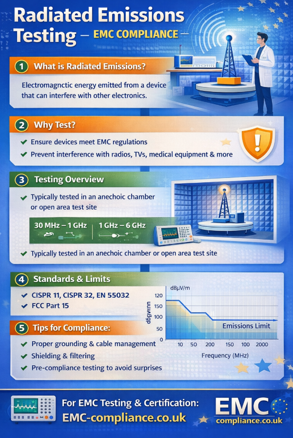
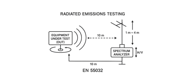
Radiated emissions testing is designed to measure the electromagnetic energy emitted from a device under test (DUT) to ensure it does not interfere with other electronic equipment. The setup typically takes place in a controlled environment such as an anechoic chamber, which absorbs reflections to simulate free-space conditions, or an open-area test site (OATS). The DUT is placed on a non-conductive turntable, often 0.8-1.5 meters above the ground plane, allowing for 360° rotation to capture emissions in all directions. Measurement antennas, usually broadband biconical, log-periodic, or loop antennas depending on the frequency range, are positioned at a fixed distance from the DUT (commonly 3 or 10 meters) and can be raised or lowered to identify maximum emission levels.
The DUT is powered and operated in its typical modes to ensure representative emissions are captured. Signals received by the antenna are fed into a spectrum analyzer or EMI receiver, which records the amplitude of emissions across the frequency range of interest (often 30 MHz to 1 GHz for low-frequency emissions and up to several GHz for higher-frequency devices). Measurements are repeated with different antenna polarizations and DUT orientations to ensure the worst-case emissions are identified. Grounding, cable routing, and environmental controls are carefully managed to avoid introducing measurement errors, and the entire setup must comply with international standards such as CISPR 11, CISPR 32, EN 55032, or FCC Part 15 to validate compliance.
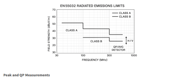
Limit lines in EN55032 define the maximum allowable levels of electromagnetic emissions from multimedia equipment to ensure compliance with electromagnetic compatibility (EMC) regulations. These limits are categorized into Class A and Class B, depending on the intended environment: Class A applies to equipment used in industrial settings, while Class B is for residential environments and is more stringent.
Limit lines for EN55032 (30-1GHz)
• Class A: Designed for industrial environments, allowing higher emissions.
• 30-230 MHz: 49.5 dBμV/m
• 230-1000 MHz: 59.5 dBμV/m
Class B: Intended for residential environments, with stricter limits.
• 30-230 MHz: 40 dBμV/m
• 230-1000 MHz: 47 dBμV/m
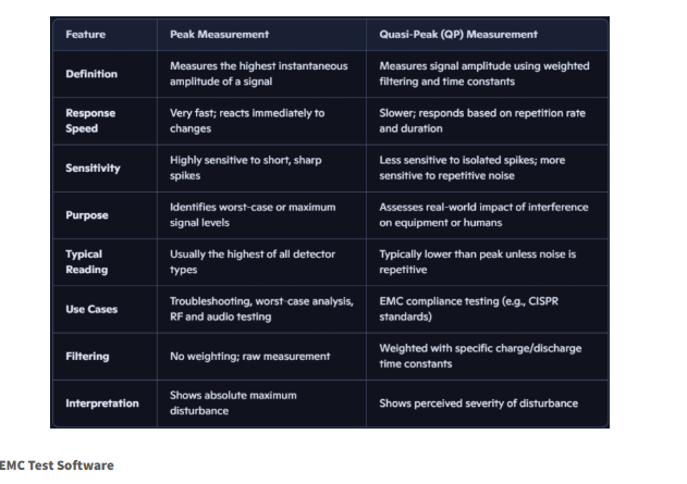
Peak and Quasi-Peak (QP) measurements are two methods used to evaluate the amplitude of signals, particularly in electromagnetic compatibility (EMC) testing and audio or RF analysis. Peak measurement captures the highest instantaneous value of a signal, making it fast, sensitive, and useful for identifying worst-case conditions. Quasi-Peak measurement, on the other hand, applies weighted filtering and specific charge/discharge time constants to reflect how humans or equipment perceive repetitive interference. As a result, QP readings are typically lower than peak values and provide a more realistic assessment of a signal’s impact on real-world systems. Together, these measurements help engineers understand both the absolute maximum levels and the practical significance of signal disturbances.
EMC32 is Rohde & Schwarz’s automation software used to control receivers, spectrum analyzers, antennas, turntables, LISNs, and chambers for EMC emissions and immunity testing. If you’re looking for a clear explanation of what the software does and how it fits into an EMC test program, here’s a crisp, practical overview.
What EMC32 Is Used For
EMC32 provides a unified environment to automate and document EMC tests, including:
1. Conducted emissions (mains, telecom, DC ports)
2. Radiated emissions (CISPR 32, FCC Part 15, MIL-STD, automotive)
3. Radiated immunity (IEC 61000-4-3)
4. Conducted immunity (IEC 61000-4-6)
5. Transient and ESD tests (when supported hardware is connected)
It replaces manual instrument control with a structured, repeatable test workflow. There are other software packages out there such as EMC View, Radimation and Elektra (R&S).